-40%
Universal Turn Signal Flasher Relay / Module
$ 13.2
- Description
- Size Guide
Description
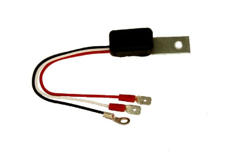
Flasher_ModuleElectronic Low Current Turn Signal Flasher Relay / Module
The Universal Flasher Module (UFM) is a simple replacement and upgrade for standard turn signal flasher relays. The UFM is compatible with incandescent lighting, LED lighting or combination of both. The flashing period is not affected by the current load placed on it. Regardless of how much or how little the current load, the module’s flashing frequency remains digitally precise. Not only is the module compatible across types of loads, it is also has a very wide voltage operating range. This makes the module suitable for vehicles using different system voltages. The UFM is constructed of solid state components that will not wear out over time, unlike mechanical relays. Being 100% solid state, the flasher module also operates silently. The module comes with 1/4 inch blade terminals to provide simple replacement for standard flash relays. Extended leads on the module allows for easy mounting and installation.
The module operates with the ground wire connected to chassis ground and the white load wire connected to an electrical load. Any time power is applied to the red power wire, power is passed through to the white load wire and power the load. The micro circuitry in the flasher module then counts out 0.3 seconds. After 03 seconds, the flasher module interrupts power to the white load wire and then counts out another 0.3 seconds. After this second count, the flasher resumes power to the white load wire. This process repeats itself until power is removed from the red power wire.
The flasher module will operate digitally accurate with operational voltages ranging from 5 volts to 18 volts with upt to 10 amps load. This makes the module suitable for a wide variety of application, such as antique cars and vintage motorcycles with 6 volt systems to modern cars and sport vehicles.
Flasher Module Benefits
Three adjustable parameter knobs can be set by the user to provide for a simple, yet very flexible, customized fuel pump operation
Provides reduced power levels to fuel pump when engine is under light power loads
Improves fuel pump longevity
Lowers or eliminates fuel heating
Reduces fuel pump noise when not under full power
Fully enclosed alloy enclosure protects circuitry
Reduces or eliminates the problem of the fuel sump being pumped empty during deceleration
100% solid state design with no mechanical relays to fail or replace
Uses regenerative power control to provide exceedingly high efficiency as well as eliminating all switching stress on the motor’s windings
Trigger input allows the module to be a secondary pump drive
The control housing incorporates an integral mounting flange for simple mounting
Integrated manifold pressure sensor for installation into conventional engine setups without electronic engine control computers and the related sensors
Incorporates fully sealed inline connectors for reliable connections
Simple Installation
The Flasher Module is compatible with all two prong flasher relay, regardless of polarity. This makes the flasher universal for all two wire flasher relays. The installation is completed in 5 simple steps and with the use of a Volt Meter, Digital Multi Meter (DMM) or even a basic test light.
Gain access to the vehicle’s turn signal flasher module and remove the flasher module.
Determine which terminal where the turn signal flasher module was attached has +12 volts.
With the vehicle’s ignition ON and using a Volt Meter, DDMM or a Test Light, connect one test lead to chassis ground and then test each of the flasher terminals to determine which one has +12 volts.
Connect the Universal Flasher Module's Black wire terminal to any good chassis ground point.
Insert the Universal Flasher Module's White wire terminal to the LOAD terminal. This will be the one that did NOT have +12 volts when tested in Step 2 .
Insert the Universal Flasher Module Red power wire terminal to the +12 volt terminal of the flasher connection determined in Step 2.
Wiring Diagram
Technical Information
Size: W – 0.6 ” L – 2.3 ” H – 0.6 ”
Weight: 1 oz. / 15 gm
Lead Length: 5"
Input Voltage: 5 - 18 Volts
Output Voltage: 5 - 18 Volts (Equal to input voltage)
Output Current (Maximum): 10 Amps
Connection Polarity: Negative ground wiring systems
Flash Frequency: 1.6 Hz (cycles On for 0.3 sec., Off for 0.3 sec.)
Internal Switching: Solid State, no mechanical relay contacts
External Connectors: ¼” blade terminals, ring terminal for ground
Maximum Ambient Operating Temperature: 120°F / 50 °C


