-40%
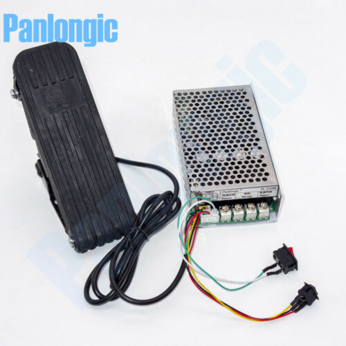
Footboard Hall Throttle 10-50V 100A Reversible PWM DC Motor Speed Controller
$ 45.93
- Description
- Size Guide
Description
10-50V 60A DC Motor Speed Control PWM Controller 12V 24V 36V 48V 3000W ESC16.99 USD
Free shipping
10-55V 60A 3KW Reversible DC Motor Speed Controller PWM Control Digital Display
22.99 USD
Free shipping
DC 40A DC Motor Speed Control Reversible PWM Controller 12V 24V 36V 48V 2000W
18.99 USD
Free shipping
12V 24V 48V 40A 2000W DC Brush Motor Speed Control PWM HHO RC Controller
9.99 USD
Free shipping
10-50V 40A DC Motor Speed Control PWM HHO RC Controller 12V 24V 48V 2000W
9.89 USD
Free shipping
10-50V 60A DC Motor Speed Control PWM Controller 12V 24V 36V 48V 3000W with Case
18.99 USD
Free shipping
10-50V 100A 5000W Programable Reversible DC Motor Speed Controller PWM HHO Control 12V 24V 36V 48V Forward Reverse Switch
Pr
oduct Feature:
Larger current, max current up to 100A, continuous operating current of up to 60A.
Reversing control motor, dual relay control, can withstand higher current.
Programmable to meet subsequent extensions.
Soft start to reduce the large current shock.
Brake after power off.
Controlling the motor speed by the foot.
Technical Specifications:
Power requirement: DC 10-50V
Rated current: 60A (Maximum output current: 100A)
Frequency: 15kHZ
Control Motor Power: 0.01-5000W,
12V: 1200W(max), 24V: 2400W(max) , 36V: 3600W(max), 48V: 4800W(max)
Standby current: 0.01A
Regulation range: 0-100%
Controller Size: 145 x 78 x 38 mm
How to use:
There are two ON/OFF switches on the controller. One is power switch, another is reversal switch.
The power switch is on, the controller is powered on. The power switch off, the motor will be brake.
The reversal switch on, the motor forward, the switch off, the motor backward.
When you press the pedal, the motor will accelerate.
Note: the pedal comes without the fix screw.
Package include:
1 X
Reversible DC Motor Speed Controller
Please check pictures for more details.
What is the PWM?
Pulse-width modulation (PWM)
is a modulation technique used to encode a message into a pulsing signal. Although this modulation technique can be used to encode information for transmission, its main use is to allow the control of the power supplied to electrical devices, especially to inertial loads such as motors.
The average value of voltage (and current) fed to the load is controlled by turning the switch between supply and load on and off at a fast rate. The longer the switch is on compared to the off periods, the higher the total power supplied to the load.
The PWM switching frequency has to be much higher than what would affect the load (the device that uses the power), which is to say that the resultant waveform perceived by the load must be as smooth as possible. Typically switching has to be done several times a minute in an electric stove, 120 Hz in a lamp dimmer, from few kilohertz (kHz) to tens of kHz for a motor drive and well into the tens or hundreds of kHz in audio amplifiers and computer power supplies.
The term
duty cycle
describes the proportion of 'on' time to the regular interval or 'period' of time; a low duty cycle corresponds to low power, because the power is off for most of the time. Duty cycle is expressed in percent, 100% being fully on.
The main advantage of PWM
is that power loss in the switching devices is very low. When a switch is off there being practically no current, and when it is on and power is being transferred to the load, there is almost no voltage drop across the switch. Power loss, being the product of voltage and current, is thus in both cases close to zero. PWM also works well with digital controls, which, because of their on/off nature, can easily set the needed duty cycle.
