-40%
20-110V 2000W Brushed DC Motor Speed Controller Board PWM PLC Governor
$ 43.15
- Description
- Size Guide
Description
20-110V 2000W Brushed DC Motor Speed Controller Board PWM PLC GovernorFeatures:
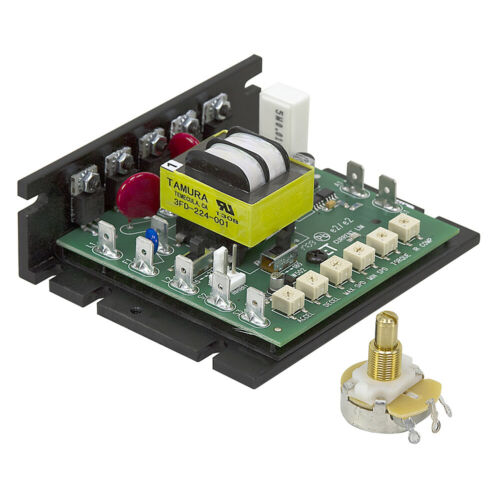
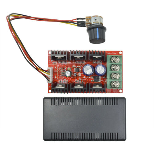
This PWM DC motor speed controller (model DM103AH) is mainly used to drive a brushed DC motor, designed for motion control cards or PLC controlling DC motor.
It has function of speed governing, on/off, CW/CCW rotation, locked-rotor alarm output, over-current protection, short circuit protection and status indication.
The speed controller can control motor with sorts of motion control cards, PLC, and also it can control motor independently.
It can be set to control different models brushed DC motors of voltage 20V-110v, and power less than 2000W.
It can be used individually through external switch and knob; can also be used with PLC, motion control card, industrial personal computer.
With complete function connector, it can connect to external 0 to 5v, 0-10v, 4-20mA, PWM signal and external potentiometer manually, a total of 5 kinds of speed governing control ways.
Designed with ON/OFF connector, CW/CCW rotation connector and protection output connector.
Support AC or DC input, there is no worry about burn-out by reverse input.Wide power supply range from AC15V to 110V (50/60Hz), DC 20V to 150V.
It has power indicator light, green light for power indicator, red light is alarm indicator.
This driver can also be used to drive boiler heat wire, vibration plate, electromagnetic machine, suitable for non-capacitive loads within 2kW.
Instruction:
1, High Voltage Connector:
M-:motor-
M+: Motor+(Limit load is 2kW, nominal load is 1.5kW, if need change rotate direction, exchange two wires)
NC: empty
ACIN: Power input (no need to distinguish "+" or "-")
Power Input:AC15V-110V(50/60Hz), DC20V-150V
2, Analog Input:
5V:Power supply 5V output pin.
AIN / VR:Analog input.This connector can connect to three kinds of signal for speed governing.
When using 0-5V/0-10V voltage speed governing or 4-20mA current signal to speed governing, need to set 4-digit DIP switch.
1)Potentiometer Speed Governing:5V, AIN/VR, GND connect respectively to three pins of a 10kR potentiometer to manually control speed; At the same time, the 4-digit DIP switch is set as "0~5V - PWM"(SW1 - ON, SW2 - OFF, SW3-OFF, SW4-ON) SW3-OFF; SW4-ON
2) :Input 0-5V or 0-10V voltage signal for speed governing.AIN/VR connects to voltage signal, GND connects to ground.
At the same time 4-digit DIP switch is set as "0~5V - PWM"(SW1 - ON, SW2 - OFF, SW3-OFF, SW4-ON
SW3-OFF; SW4-ON;
No resistor is needed for 0-5V voltage signal input, directly connect to AIN/VR &GND
Two resistors should be added for 0-10V voltage signal input as wiring in the diagram below:
3)Input 4-20mA signal for speed governing.AIN/VR connects to current signal, GND connects to ground.At the same time, 4-digit DIP switch is set as "4-20MA - PWM" (SW1-OFF, SW2-ON, SW3-OFF, SW4-ON) SW3-OFF; SW4-ON
GND: common ground (hot ground, do not touch when power on)
ON/OFF: Motor ON/OFFit can connect to an external switch.When not connected to GND, motor is on; when connected to GND, motor is off.The external ON/OFF switch connect respectively to ON/OFF and GND.
5V:Power supply 5V output pin.
CW/CCW: motor CW/CCW control connector.Recommended minimum control interval is ≥1.5 seconds to protect motor brush.External CW/CCW switch connect respectively to CW/CCW and 5V connector.
3, Digital Control Connector (isolation) :
Outside PWM: External PWM signal input for speed governing
PWM Duty Cycle Range:0-100%
PWM Frequency Range:800Hz-30kHz, recommend using 16kHz, low level effective.
Using External PWM Signals for Speed Governing:4-digit DIP switch is set as "0~5V - PWM"(SW1 - ON, SW2 - OFF, SW3-OFF, SW4-ON SW3-ON SW4-OFF
DIR: Motor direction control connector.Low level effectiveRecommended minimum control interval is ≥1.5 seconds to protect motor brush.When using external PWM signal input, you can also use an on-off switch to control CW/CCW; 2 wires of switch connect respectively to DIR and COM+5V.
EN:Motor enable control pin.When this pin is connected to low level, motor does not run.Low level effective.When not connected or connected to high level, motor runs.When using external PWM signal input, you can use an on-off switch to control on/off; 2 wires of switch connect respectively to EN and COM+5V.
COM+5V: Common wire for above three control signal.If connected to PLC24V level control, the pin should be connect to a 1.5K-3KΩ resistor in series.
NPN-C: Alarm signal output NPN transistor.When alarming, the transistor is conducted.Maximum Current: 15mA Voltage Range:3.3-24V.
NPN-E: Alarm signal output NPN transistor emitter.
4, DIP Switch Settings:
1) Analog Control Connector Signals Setting:
0-5V - PWM: When input signal is 0-5V or 0-10V voltage input or connected to external potentiometer for manual speed governing, setting is SW1-ON, SW2-OFF, SW3-OFF, SW4-ON
4-20mA-PWM: When using 4-20mA current speed governing, setting is SW1-OFF, SW2-ON, SW3-OFF, SW4-ON
2) Digital Control Connector Signal setting:
Outside PWM: When using external PWM input signal for speed governing, setting is SW1-OFF, SW2-OFF, SW3-ON, SW4-OFF
5, Over-current potentiometer, current input potentiometer, PWM frequency potentiometer setting:
1) Overcurrent/Stall Protection Potentiometer (OCP-SET) settings:
Current protection potentiometer, you can set motor over-current protection.OCP-SET adjust potentiometer is motor over-current protection setting potentiometer, function is to stop motor and protect motor, driver from burning-out when motor is over-current or locked-rotor, in the mean time, output protection signal to the PC controller for PLC or control card protection.
Setting "OCP-SET" potentiometer position.Correspondence is as follows:
A:In general, a brushed DC motor has large starting current and motor direction reversing current is also large.Normally it can reach about 5 times of motor no-load current or more.So when setting the motor over-current protection, it could be larger.
B:According to situation, adjust the rotation speed as highest, the rotating speed is set to the highest, power off then power on without protection, set point a little larger of red light turning on.If you do not need this function or motor load may change greatly, simply set potentiometer clockwise as the maximum.
2) 4-20mA signal input potentiometer (4-20 ma - ADJ) signal matching Settings:
Current Input Speed Governing Signal "4~20mA-ADJ" Potentiometer setting:
When potentiometer is used for 4-20mA signal speed governing, control correspondence of signal and rotating speed .Generally it does not need to adjust.If it is found that the actual rotating speed and control signal is not corresponding, you can adjust the potentiometer slightly.
3) PWM Signal Input Frequency Potentiometer (PWM - FRQ) Setting:
When setting as external PWM input (namely potentiometer manual speed governing, 0-10V/0-5V voltage speed governing, 4-20mA current speed governing), motor speed governing uses PWM signal produced by driver inner MCU.At this point, the potentiometer can set PWM frequency of motor speed governing.Default is 16kHz, generally don't suggest to change.
If change this setting, working noise of motor, efficiency and machinery resonance point will be changed.You may change this potentiometer setting when default settings isn't suitable for your requirement of work noise, efficiency and resonance.Clockwise to increase frequency, and counterclockwise to reduce frequency. Adjusting range is 2-20kHz.
Other Setting:
1, Support AC or DC input, voltage range DC:+20~+150V, AC:15~110V.
1) Usually we convert 220V/380V to 110V with a transformer.
2) In some countries, the voltage is 115V, 120V or 127V which will damage the driver. For example, this driver can connect to mains power in Japan directly, but not United States.
3) A transformer is suggested to use and convert mains power into less than 110V to power the driver.
4) Power capacity of power supply transformer depends on load of motor, normally is motor nominal power/0.8 and can be a litter larger. For example, 500W motor, 500/0.8 = 625W, choose 600W or 650W transformer
External Control Wiring:
Speed controller be used with PLC, MACH3 control card, SCM for speed governing.
For PLC
Set 4-digit DIP switch as "Outside PWM"(SW1-OFF, SW2-OFF, SW3-ON, SW4-OFF)
1)COM+5V: Connect a resistor (1.5kR-3kR) in series to COM or power 24V+ of PLC.
Outside PWM: Connect to PWM signal IO connector of PLC
2) Use a high/low level IO1 connector to connect DIR,
3) Use a high/low level IO2 connector to connect EN,
For MACH3 Control Card
Set 4-digit DIP switch as "Outside PWM"(SW1-OFF, SW2-OFF, SW3-ON, SW4-OFF)
COM + 5V:Connect to MACH3 control card 5V
Outside PWM:PWM signal of MACH3, some control card use P1 connector, some use P17.
Package Includes:
1 x
Speed Controller
We accept PayPal only.
We only ship item to your PayPal verified address.
Payment must be received within 3 days from the date of purchase.
All the items will be dispatched within one business day by Airmail after the payment is clear.
Most times you will receive your order within 10-30 business days after we transfer your package to the delivery company. We cannot guarantee the delivery timeframe if the post office has any unexpected delays due to holiday, weather, customs, or other conditions. Some countries like Russia, Brazil, or some European countries may take up to 50 days or longer for delivery.
We appreciate your patience if you haven't received items in 30 days(Russian customers may need more patience by reason of the local delivery system and/or customs). If you are concerned in any way, please feel free to contact us via ebay message
instead of leaving negative/neutral feedback or opening a dispute
.
We will make every effort to fix any problem(resend or refund any missing item).
Customs duty is obligation and liability of
citizen
s in your country, so buyer should be responsible for any tax and custom duty incurred. Generally, the delay or failure delivery is sometimes caused by the policy of different customs.
1. Our listing price includes the value of goods,packaging cost,and export
taxes,not including international import duties.
2. Import duties,taxes,and charges are not included in the item price or shipping fee.
3.
T
he import duties are buyers' responsibility
.Please check with your country's
customs office determine what these additional costs will be prior to your
purchase.
4. All disputes arising from the import duties will be submitted to ebay for solution.
1. Any questions,
pls. contact us via ebay message or email us.
We will reply your message within 48 hours. If you do not receive our reply within 48 hours, pls. post a message again because sometimes our message system may block some emails.
2. If you are satisfied with our service, pls. kindly leave us a positive feedback and give us the Detailed Seller Rating with all "
5 stars
" in very area
3. Our aim is to provide Top Level Customer Service, your recognition will encourage us greatly and serve you better.
We strive to keep all our customers satisfy.
We will always do our up most to exceed your expectations in customer service, communication and dispatching of your orders.


